Chapter 5 - Liquefier Acqusition and Control Computer
Safe Mode and Emergency Safe Mode
Automated purity readings and interlock
Liquid Helium dewar-to-dewar transfer shut-off interlock
Peripheral files
View website PDF document
Hi-res video: Building a helium recovery system (5 minutes long)
YouTube video: Building a helium recovery system (5 minutes long)
List of many parts with prices and links [xls]
Chapter 5 - Liquefier Acqusition and Control Computer
 A
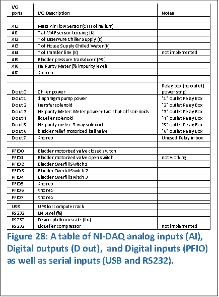
summary of the current data acquisition card (NIDAQ) IO’s and computer serial
ports are listed in Figure 28. Sensors are read through the analog inputs (AI),
digital inputs (PFIO), and serial (USB and RS-232) ports. Control of system components
is actuated through a relay box using digital outputs (D out).
A
summary of the current data acquisition card (NIDAQ) IO’s and computer serial
ports are listed in Figure 28. Sensors are read through the analog inputs (AI),
digital inputs (PFIO), and serial (USB and RS-232) ports. Control of system components
is actuated through a relay box using digital outputs (D out).
A Labview program measures analog inputs from the helium mass flow (MF) sensor, multiple 1kOhm RTD thermometers (MF thermometer, chiller coolant supply, and House chilled water supply), bladder pressure transducer, and Helium purity meter. The status of the power to the battery backup system on the computer rack is monitored over a USB connection. The LN level of the cold trap dewar is measured over a serial connection to the American Magnetics LN level controller. The liquid level of mobile dewars is monitored by acquiring scale readings (in lbs) over the serial port.
The motorized over/under- inflation bladder valve has onboard switches to indicate when the valve is fully opened or closed. The status of these switches are read by digital inputs. The status of three bladder overfill switches are similarly measured.
The computer controls solenoid valves and power to equipment using digital outputs that set the state of eight 120V relays. Power to the chiller, diaphragm pump, and helium purity meter is computer controlled. Two-way computer controlled solenoid valves are mounted on the Transfer MAF Assembly (see Figure 9), the input of the LHeP22 (see Figure 11a), and to the helium purity meter (2 of them). One three-way solenoid valve is also mounted to the helium purity meter (see Figure 1b). The computer also controls a motorized ball bladder-relief valve (see Figure 19a).
 Teamviewer
is installed on the Liquefier computer and the LHeP22 computer. Both machines
are accessible remotely. Charting and status indicators are remotely viewed,
logfiles downloaded and analyzed, and equipment manually controlled remotely.
Teamviewer
is installed on the Liquefier computer and the LHeP22 computer. Both machines
are accessible remotely. Charting and status indicators are remotely viewed,
logfiles downloaded and analyzed, and equipment manually controlled remotely.
The bladder level is remotely monitored in real-time by accessing the bladder security camera. The Liquefier computer uses ISpy security software to take snapshots of the bladder every hour. Downloading the time-lapse history of the level of the bladder is a powerful diagnostic which can be remotely accessed and analyzed.
Mathematica software reads the log files from both the Liquefier and LHeP22 computers for charting and diagnostics.
A Safe Mode is instigated by the program under certain conditions. In this mode, the liquefier solenoid valve closes protecting the LHeP22 from impurities. The diaphragm pump is turned off. The purity meter solenoid valves are shut stopping helium flow, and the meter power is de-energized. In this mode, the chiller and bladder over-/under- inflation interlocks remain active.
The Emergency Safe Mode can only be cleared manually by the user.
 The
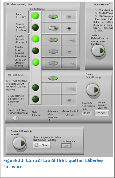
control tab of the Labview program is shown in Figure 30. The conditions
depicted in The rows are, from top to bottom, the diaphragm pump, transfer
solenoid, liquefier solenoid, bladder relief solenoid, and chiller power. The
remaining two rows are associated with the helium purity meter. These are the
controlled processes.
The
control tab of the Labview program is shown in Figure 30. The conditions
depicted in The rows are, from top to bottom, the diaphragm pump, transfer
solenoid, liquefier solenoid, bladder relief solenoid, and chiller power. The
remaining two rows are associated with the helium purity meter. These are the
controlled processes.
The first column is the status of the process. The second column contains a switch that, when lit, allows the computer to control the process (automatic mode). The third column is a manual switch that the user toggles to control the process. Automatic readings of the helium purity meter are activated with one switch.
An important button to note is at the bottom, “Clear Emergency Safe Mode”.
Figure 30 shows the normal operating configuration while liquefying. The computer controls the diaphragm pump, liquefier solenoid, bladder relief solenoid, and chiller power. Reading of the helium purity meter is automatically controlled.
A computer program controls the power to the meter and three solenoid valves to control the flow. A three-way solenoid valve allows switching one chamber (labelled “sample gas” on the meter) between reference gas and sample gas. The three-way valve is normally open for the reference gas channel but normally closed for the sample gas. One on/off solenoid valve controls the flow of the reference gas. Another on/off solenoid valve controls the combined sample and reference exhaust gasses that eventually flow into the Liquefier Manifold (see Figure 11b) and routed to the bladder. The meter power and the two on/off solenoid valves are controlled by one relay. The three-way valve is controlled by a second relay. With the automated measurements every 2 hours, a single 300 cuft cylinder of 5.0 reference He gas is estimatead to last 1 year before requiring replacement. The flow rate through the anemometer chambers must be approximately equal and adjusted so that the ball bearings in the rotometers are at ½ to 2/3 of full scale.
Note that the meter must be manually zeroed before automating purity measurements. The zero will drift some amount, so automated measurements include calibrating the zero. However, the zero must be coarsely correct, otherwise the dynamic range of the amplifiers that output the voltage at the analog output could become saturated which would throw off impurity measurements.
The sequence of the automated reading is as follows. The meter is turned on concurrently with the pure helium reference gas flow, and the helium exhaust ports (for both sample and reference gasses) is opened. A user defined delay (90 seconds) allows the lines and anemometer chambers to be flushed and the hot-wire anemometers to warm up. Reference gas flows through both anemometer chambers to measure the zero impurity voltage. The impurity level, averaged over some user defined interval, is consecutively measured with a delay between readings. The user defines the settling tolerance required between consecutive measurements (set to 0.01%). The meter continues to take impurity readings until the criteria is met by the last two readings. Fault flags are set if either the voltage is out of range or the maximum number of readings has been breached. Otherwise, the new “zero” impurity level voltage Vz is recorded.
Next, the 3-way solenoid valve is energized so that sample
gas flows through the Sample anemometer. The sequence of impurity level is the
same as before: flush the helium lines and Sample anemometer chamber, take and
average readings, delay, etc., until the meter has settled within a user
defined tolerance. If no fault occurs, then the impurity level is found from
the new sample voltage Vs by ![]() where
where
![]() is the calibrated slope (see Appendix 2).
is the calibrated slope (see Appendix 2).
If the impurity level of the sample gas is greater than a threshold defined by the user (currently 0.021%), then the program instigates Emergency Safe Mode and liquefaction stops.
The chiller operates continuously under normal conditions. However, if the house supplied chilled water supply is turned off or no longer cold, then the small closed-loop coolant continuously heats up due to the heat generated by the water pump even with the LHeP22 compressor off. To prevent excessive temperatures, a computer controlled interlock has been implemented.
The chiller’s on/off switch is wired in parallel to a computer controlled relay. With the power switch off, the computer controls the power to the chiller. If the temperature of coolant breaches a user defined threshold, the chiller is powered off. The threshold is sufficiently high that the LHeP22 compressor automatically turns off before the chiller is powered off.
A dewar-to-dewar liquid helium transfer is automatically controlled when the user presses the “instigate a helium plant to mobile dewar transfer” button shown in Figure 30. Selecting the button enables the interlock. When activated, breaching a maximum dewar weight, minimum temperature measured by the MAF thermometer, or a maximum time duration closes the transfer solenoid (see Figure 9).
Closing the transfer solenoid valve terminates the transfer since the pressures in the 150L dewar and the mobile dewar equalize.
The bladder is outfitted with a high flow -0.22 PSIG vacuum breaker relief valve that prevents catastrophic evacuation that may damage the bladder.
Active interlocks are also required as the system is liquefying. Without an active interlock, the diaphragm pump continues to pump even when the bladder has been emptied and the relief valve is open, dumping large amounts of air into the system and quickly saturating the water and cold traps. A pressure transducer near the bladder measures pressure to 0.01 PSIG. An under-pressure of -0.15 PSIG triggers Safe Mode. By shutting off the diaphragm pump, creasing of the bladder and stress on the bladder near the flange from evacuation is also minimized.
After a user defined time interval passes, the Safe Mode is revoked and the system begins liquefying again. This allows the system to periodically empty the bladder of any helium that was recaptured in the interim.
Over-inflating the bladder is problematic in a closed room.
A small pressure integrated over the entire area of a cinderblock wall can be
enormous. Therefore, interlocks are required but passive interlocks only
operate to pressures down to around 0.1 PSIG. Such a pressure on a single
cinderblock is ![]() is
therefore 13 lbs. One of the bladder room walls is about 200 cinder blocks, so
this small pressure could potentially create about 1.3 tons of outward force.
is
therefore 13 lbs. One of the bladder room walls is about 200 cinder blocks, so
this small pressure could potentially create about 1.3 tons of outward force.
To guard against over-inflation conditions, the bladder should never be nearly full when the magnet is in use in case of a quench. The reservoir of the magnet is 20LLHe, or about 15% of the bladder capacity. Large catastrophic rapid release of helium into the recovery system cannot happen by any other mechanism.
Active interlocks also guard against over-inflation. Three switches are located in the bladder room. If the bladder over inflates and trips one, an automated alert message is emailed to the user. If any two of the three switches are tripped, a 2” motorized Ball valve is opened until all three switches are closed.
If the LN level drops below a user defined level due to a fault in the refill system or perhaps an empty LN refill dewar, then an Emergency Safe mode is triggered. Since the effects due to low LN level are high helium impurity levels, this interlock is somewhat redundant since helium purity readings are now automated.
The power to the room is monitored by the UPS (uninterruptable power supply) connected through the USB port. If the power goes out, Safe Mode is instigated. If the power remains off and the UPS batter level drops to a critical threshold (set in the windows operating system), the computer institutes an Emergency Safe Mode and then powers itself down.
Cryomech has built into the LHeP22 a number of interlocks. If the compressor oil temperature becomes too high (>126F), then the compressor controller shuts off and reports errors. If brown outs occur, then the compressor may shut down and report odd error codes. Under these conditions, the LHeP22 will beep until the system is reset. To reset, switch the main breaker on the LHeP22 off and then on. Read the Cryomech manual regarding other interlocks.
Automatic controls tend to automatically screw up. An extra safety mechanism prevents rapid energization and de-energization of any computer controlled process. The logic evaluation and control section of the program loops rapidly, many times per second. Rapid on-off conditions can damage equipment. Longer time scale on-off conditions integrated over many unattended days can be extremely detrimental to electronics. Therefore, the status of each controller is monitored and evaluated. The user defines the maximum number of on/off cycles that can occur over three time scales, currently set at half a second, 30 seconds, and an hour. If any of these three conditions are breached, the Emergency Safe Mode is instigated.